|
9:1 VOLTAGE UNUN
9:1 voltage unun using a T-200-2 powdered iron
toroid core
With
the view to establish a quick and easy multi-band antenna deployment
for portable and camping operations a simple long wire antenna with
an earth or earth plus counterpoise arrangement with a 9:1
voltage unun is one possible solution.
Requiring
a unun to feed a long wire antenna ideally without a tuner a 9:1
voltage unun
design using a T200-2
Toroid core was selected.
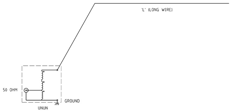
Figure
1 Typical
9:1 voltage
unun and long wire antenna configuration.
Construction
PVC
covered 1mm diameter copper wire was used with the view that the
thicker insulation may reduce the possibility of insulation puncture
due to the higher nominal impedance.
The
triple bifilar winding of 10 turns are wound evenly spaced around the
T-200-2 powdered iron toroid
core with the three individual windings wound close together.
A Green binding posts was selected to clearly identify the common
earth connection.
The
length of enamelled copper wire per winding for the T-200-2 powdered
iron toroid core
is determined by length per winding = 50mm per turn plus 250mm
tails.
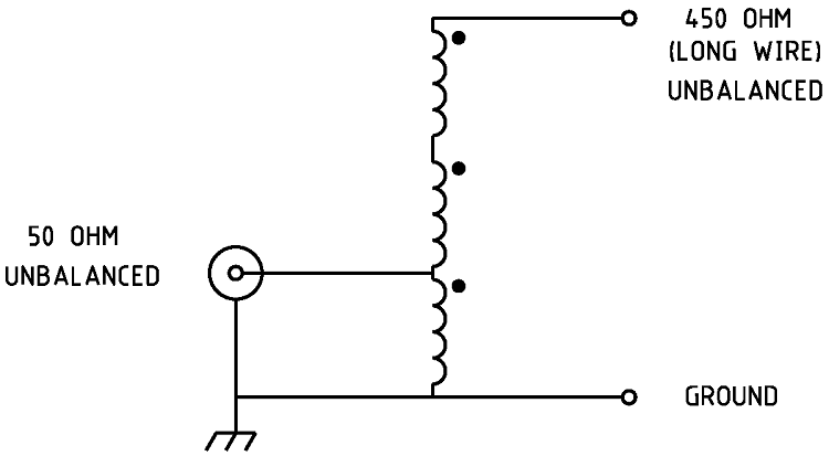
Figure
2 Schematic of the 9:1 voltage
unun.
Typically unbalanced = 50/75 ohms too unbalanced = 450/675 ohms.
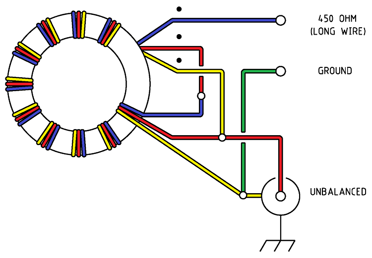
Figure
3 Wiring of the 9:1 voltage
unun.
Note
this drawing shows winding connections and not the number of turns
required. See article for details.
|
TOROID
|
NUMBER
OF TURNS
|
POWER
RATING
|
|
T200-2
|
9
|
400
Watts
|
Table
1 Toroid core with winding suggestions.
Parts
list.
-
T-200-2
powdered iron toroid core from Amidon
-
About
750mm of 1.0mm Covered copper wire per winding.
-
Black
and Green binding posts
-
SO-239
UHF chassis mount connector
-
Sealed Polycarbonate Enclosures 82 x 80 x 55mm
from Jaycar. See
Fig 4 for details
Figure 4 Sealed Polycarbonate Enclosures 82 x 80 x 55mm
details
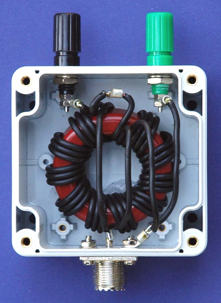
Photo 1
9:1 voltage
unun
assembled.
The
evaluation of the efficiency of the unun over the desired bandwidth
(1.8 - 30MHz) was carried out by testing the impedance that could be
seen from transceiver
side of the unun
to
a resistive load applied to the antenna side of the unun using an
antenna analyser. The efficiency is shown to cut of sharply below
5MHz and gradually taper off at about 30MHz. The below antenna
analyser plot viewing a 450ohm resistive load attached to the
balanced side of the balun and measured at a nominal impedance of
50ohms presented as anticipated an approximate 50ohm load to the
analyser and produced about a 1:1 SWR. Despite not having carried
out this test previously the results are more or less what was
expected and demonstrates that the unun's 1:9 voltage transformation
occurs efficiently from 7 to 25MHz. The results are not as
satisfying as those carried out on the 1:1 voltage balun showing
significant reactance across the band. The results are less than
ideal and the application of the design is to be reviewed, but is
useful over a limited frequency range from 7MHz to 25MHz.
Figure
5
AIM
4170C antenna analyser plot viewing a 450ohm resistive load through
the unun.
Note the 450ohm resistor appears as 50ohms due to the 9:1
unun
ratio resulting in an ideal SWR of 1:1.
AIM 4170C antenna analyser explanation;
|
SWR
|
Standing Wave Ratio.
|
|
Zmag
|
Total Impedance.
|
|
Rs
|
Resistive component of the total impedance
|
|
Xs
|
Reactive component of the total impedance also indicating the +/-sign
of the value. Inductive being a positive value and capacitive
being a negative number.
|
|
Theta
|
Phase angle between voltage and current.
|
|
Return Loss
|
Total reflected system loss.
|
An
additional evaluation of the efficiency of the unun was preformed by
simply measuring the RF power at selected frequencies fed into the
balun and measuring the out put power from the balun using the set
up shown in Figure 8. In this set up it was necessary to have two
identical 9:1
ununs, the second to step the impedance back down to the 50 ohms for
measuring. It is critically important that the two ununs be made in
a identical fashion as the results need to assume that half the
losses are as a result of each of the ununs as that the below formula
simply halves the resultant overall loss.
For
example, RF was applied to the input of the unun at a frequency of
1.8 MHz at a power of 5 Watts with 0.45 Watts being measured at the
output meter. The below formula was applied revealing a Balun loss
of 5.2dB at this frequency per unun.

Figure 6 shows the results of measurements taken at various frequencies
including the calculated loss. Figure 7 shows the graphed results of
the losses verses frequency.
Concussion of this evaluation is that the efficiency between 8.0 MHz to
25 MHz is very low as to be unnoticeable and that even at 25 to 30 Mhz the
loss would be almost unnoticeable however the losses are high at 3.5
MHz representing a full 'S' point drop or half the power being lost in
the unun. At 1.8 MHz the losses are very high at -5.2 dB, almost 2 'S'
points. This unun should be useful from
7.0 MHz to 30 MHz and at push on 3.5MHz if nothing better was
avaliable.
The limitation of this evaluation is that it is under an ideal situation
of 50 ohms and that more extreme loads will likely show greater
losses.
|
Freq
|
Input
PWR
|
Output
PWR
|
dB
Loss
|
|
1,60
|
5,00
|
0,40
|
-5,5
|
|
1,80
|
5,00
|
0,45
|
-5,2
|
|
3,60
|
5,00
|
1,20
|
-3,1
|
|
7,10
|
5,00
|
3,40
|
-0,8
|
|
10,10
|
5,00
|
4,32
|
-0,3
|
|
14,50
|
5,00
|
4,90
|
0,0
|
|
21,10
|
5,00
|
4,50
|
-0,2
|
|
28,10
|
5,00
|
3,10
|
-1,0
|
|
29,70
|
5,00
|
2,75
|
-1,3
|
Figure
6
Table of test results.
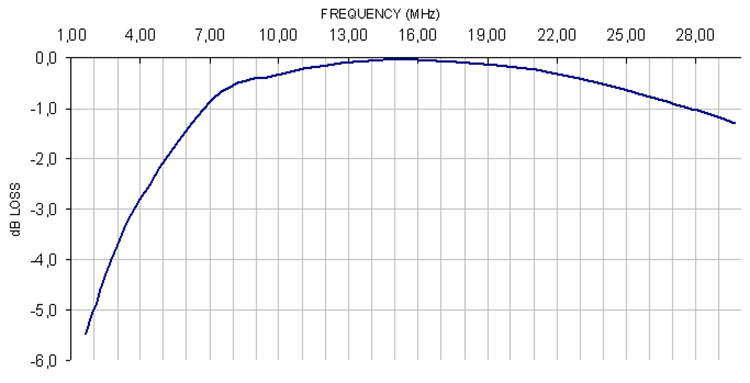
Figure
7
Plot of Balun losses verses frequency.
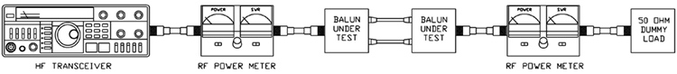
Figure
8
Efficiency evaluation set up.
Also
see other baluns and ununs:
BALUN
1:1 CHOKE & 1:4 BALUN HF
ladder feed-line to coaxial cable combination choke and 1:4 balun.
(0.1MHz - 30MHz).
BALUN 1:1
CHOKING Choking balun for
lower HF and MF bands. (200kHz - 10MHz).
CHOKING
1:1 BALUN - HF BANDS Reisert choking balun.
(1.0MHz - 30MHz). FT240-43 Ferrite Toroid Core.
CHOKING
1:1 BALUN - HF BANDS Reisert choking balun (1.5MHz - 30MHz). FT140-43
Ferrite Toroid Core.
CHOKING
1:1 BALUN - LOW VHF BAND Choking balun.
(10MHz - 60MHz). FT140-43 Ferrite Toroid Core.
BALUN
1:1 CURRENT 1:1 Guanella Current balun using a L15
ferrite core (1.8 - 30MHz).
BALUN
1:4 CURRENT 1:4 Guanella Current balun using a L15
ferrite core (1.8 - 30MHz).
BALUN
1:4 SINGLE CORE CURRENT 1:4 Guanella Current Balun, single FT240-43
ferrite toroid cores. (0.3MHz - 30MHz).
BALUN 1:1
VOLTAGE 1:1 Ruthroff voltage balun using a T-200-2 powdered iron
toroid core (1.8 - 30MHz).
BALUN 4:1
VOLTAGE 4:1 Ruthroff voltage balun using a T-200-2 powdered iron
toroid core (1.8 - 30MHz).
BALUN 6:1
VOLTAGE - VERSION 1 6:1 Voltage balun using a L15 ferrite toroid core (1.8 - 30MHz).
BALUN 6:1
VOLTAGE - VERSION 2 6:1 Voltage balun using a FT140-43 Ferrite
Toroid Core (1.8 - 30MHz)
BALUN 9:1
VOLTAGE - VERSION 1 9:1 Voltage balun using a L15 ferrite toroid core (1.8 - 30MHz).
BALUN 9:1
VOLTAGE - VERSION 2 9:1 Voltage balun using a FT140-43 Ferrite
Toroid Core (0.5 - 60MHz).
UNUN 9:1
VOLTAGE 9:1 voltage unun
using a T-200-2 powdered iron toroid core (1.8 - 30MHz).
UNUN 9:1
VOLTAGE VERSION 2 9:1 voltage unun using a L15 ferrite core (1.8
- 30MHz).
UNUN 9:1
VOLTAGE VERSION 3 9:1 voltage unun using a FT140-43 ferrite core
(0.5 - 60MHz).
References
Martin Ehrenfried G8JNJ
experimentation with baluns and ununs see: http://g8jnj.webs.com/balunsandtuners.htm
TOP
OF PAGE
Page
last revised 05 May, 2025
|


