|
DISH ANTENNA - 1.7GHz
Satellite
Dish Antenna - 1.7 Ghz. October 2025. Under
development
This project focuses on the design, construction, and testing of a dish antenna system
optimised for 1.7 GHz (L Band) reception. The goal is to reliably receive images and data transmissions from geostationary weather satellites and other space-based signal sources operating in this band.
Issues
covered are the antenna geometry and feed design, Low-noise
amplification and filtering. Careful attention is given to achieving low system noise, precise alignment, and stable performance suitable for continuous satellite monitoring.
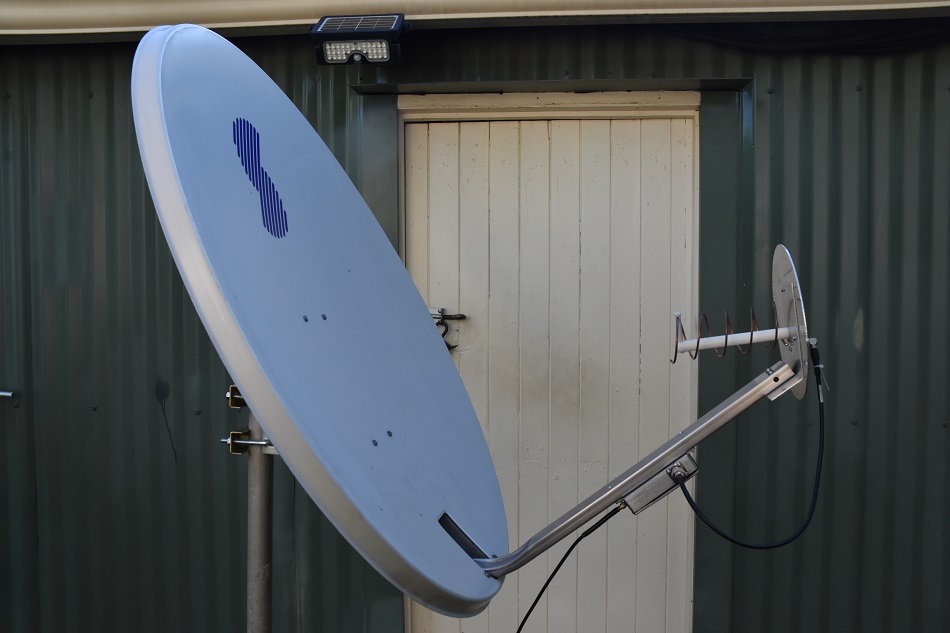
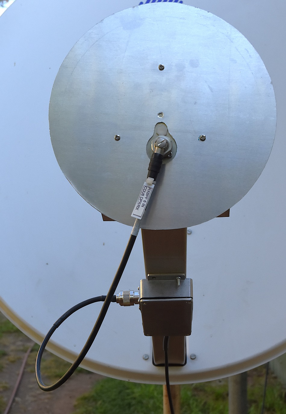
Photo
1 Shown is the completed 1.7 GHz (L Band)
antenna including the Nooelec SAW Filter & Ultra-Low Noise LNA Module.
The antenna system is based on a repurposed 0.9-metre offset satellite TV dish, adapted for reception in the L-band around 1.7 GHz. The reflector provides substantial gain and a narrow beamwidth, ideal for receiving continuous signals from geostationary weather satellites.
At the feed point, a custom-designed helical antenna is mounted at the dish’s focal position.
Signal amplification and filtering are handled by a Nooelec SAWbird+ GOES Barebones module,
with integrated SAW filter cantered at 1688 MHz and a cascaded ultra-low-noise amplifier (LNA). This configuration provides excellent out-of-band rejection and a very low noise figure, improving system sensitivity and overall signal quality.
Parabolic Reflector Antenna Gain Calculator
Where,'D' is the diameter of the parabolic reflector dish, and'λ' is the wavelength of the antenna
Calculated
gain for this size dish at 1.7Ghz should be approximately 22dB.
everything RF
- Parabolic Reflector Antenna Gain Calculator
https://www.everythingrf.com/rf-calculators/parabolic-reflector-antenna-gain
Helical Antenna Calculation

Design frequency
1690MHz
Number of turns 5
Turn spacing 0.23
wavelengths
| Wavelength: |
|
177.5mm |
|
| Ideal diameter
(internal) |
D |
60.2mm |
|
| Conductor diameter |
d |
3.5mm |
|
| Winding step
(between centres) |
S |
40.8mm |
|
| Separation of the
adapter section |
a |
1.7mm |
|
| Minimum reflector
diameter |
R |
110 mm |
|
| Total antenna length |
L |
204.1mm |
|
| Total conductor
length |
|
967.9mm |
|
Design performance
| Gain |
10.27
dBi |
|
| Bandwidth (@ -
1dB) Fmax/Fmin: 1.07 |
Fmax:
1752.37MHz |
|
|
F
min: 1629.84MHz |
|
| Bandwidth (@ -3dB)
Fmax/Fmin: 1.24 |
Fmax:
1883.69MHz |
|
|
Fmin:
1516.22MHz |
|
| Beam width (@ -3dB) |
48.4degrees |
|
John Coppens ON6JC/LW3HAZ - Helix antenna design and construction details
https://jcoppens.com/ant/helix/calc.en.php
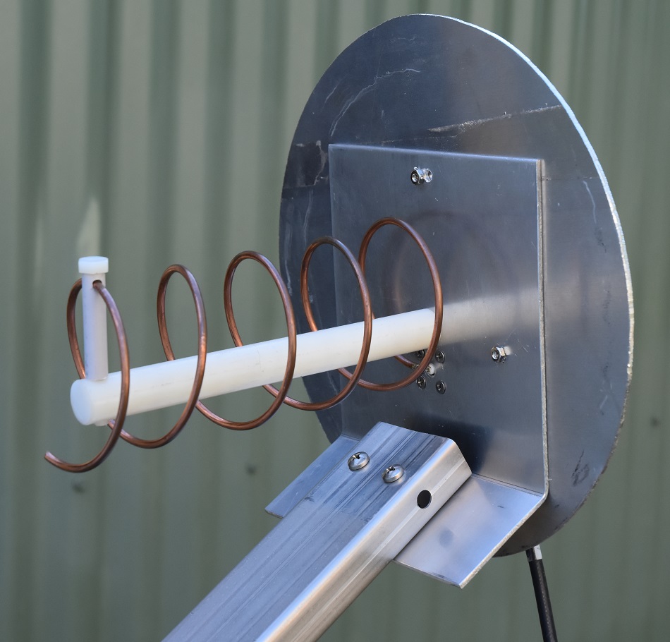
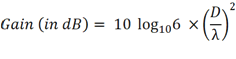
Photo 2 Shown
is the Helical focal point Antenna.
Testing
Photo
3 The Helical focal antenna under test with the NanoVNA
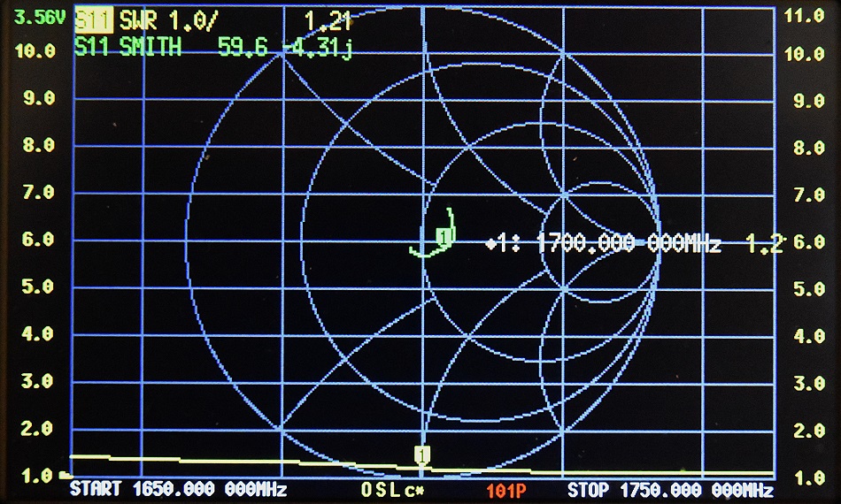
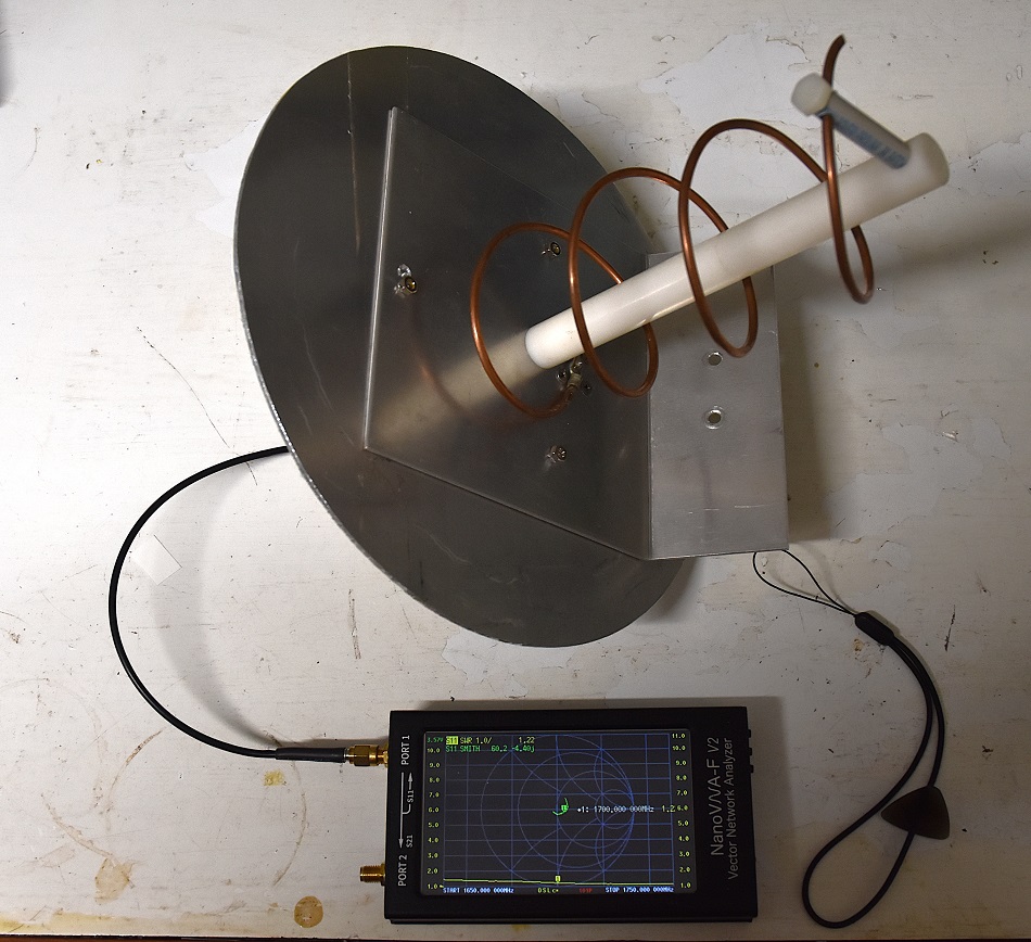
Photo
4 NanoVNA SWR and Smith Chart results, showing the SWR being
blow 1.5:1 from 1.65GHz to 1.75GHz and an impedance of 59.6 -4.31j
at 1.70GHz. and 64.3 +0j at 1.6912Ghz indicating resonance at this
frequency.
LNA (Low Noise
Amplifier)
Nooelec SAWbird+ GOES Barebones - Premium SAW Filter & Cascaded Ultra-Low Noise LNA Module for NOAA (GOES/LRIT/HRIT/HRPT) Applications. 1688MHz Center Frequency.
See details:
https://www.nooelec.com/store/sawbird-plus-goes.html?srsltid=AfmBOorbzpQso1dzClgAhUvCT7wGGg79cxf3KifFYg7wsmvmC14Cn_9z
Features
38dB
of RF gain at 1694MHz
70MHz
3dB bandwidth
2-stage
high-quality MMIC amplifiers
+3.3
– 5V single supply
Three
DC powering options
140mA
nominal current draw
50Ω
matched input/output
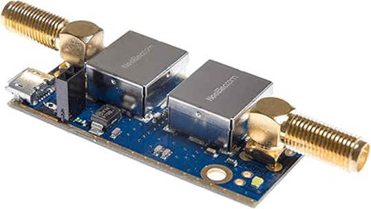
Photo
5 Nooelec SAW Filter &
Ultra-Low Noise LNA Module
Specifications:
|
Parameter
|
Symbol
|
Min
|
Typical
|
Max
|
Unit
|
|
3dB
Bandwidth
|
BW
|
-
|
70
|
-
|
MHz
|
|
10dB
Bandwidth
|
BW
|
-
|
80
|
-
|
MHz
|
|
Center
Frequency
|
fo
|
-
|
1688
|
-
|
MHz
|
|
Gain
|
S21 @
fo
|
-
|
-
|
38
|
dB
|
|
Input
Return Loss
|
S11 @
fo
|
-
|
-
|
-12
|
dB
|
|
Output
Return Loss
|
S22 @
fo
|
-
|
-
|
-15
|
dB
|
|
Output
P1dB
|
OP1dB
|
-
|
20
|
-
|
dBm
|
|
Noise
Figure total
|
NF
|
-
|
1.2
|
-
|
dB
|
|
Noise
Temperature total
|
Tn
|
100
|
110
|
120
|
K
|
|
Supply
Current
|
Isupply
|
120
|
140
|
160
|
mA
|
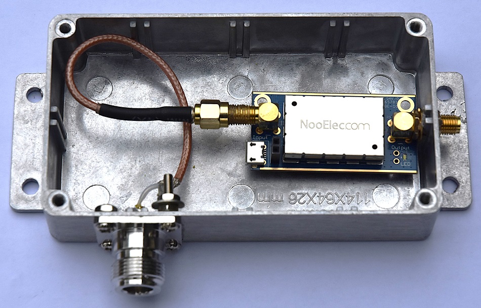
Photo
6 Nooelec LNA Module installed in a water proof encloser.
Photo
7 Nooelec LNA Module attached to the antenna.
Operational
Notes:
Details
of geostationary weather satellites that broadcast in
the 1.7 GHz (L Band) for my location in Northam west Australia.
wx_satellites_geostationary_lband_20251018.html
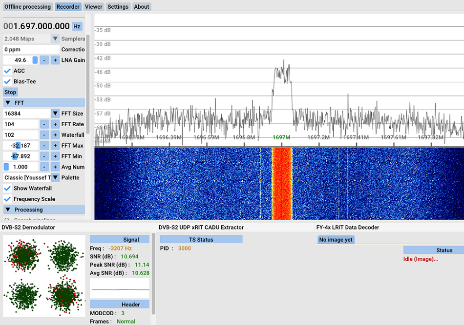
Photo
8 Reception with SatDump
software of the Chinese weather satellite FengYun-4A (FY-4) with the signal
at approximately 10dB above the
noise floor, only just barely sufficient for data recovery.
References
John Coppens ON6JC/LW3HAZ
- Helix antenna design calculator:
https://jcoppens.com/ant/helix/calc.en.php
everything RF
- Parabolic Reflector Antenna Gain Calculator
https://www.everythingrf.com/rf-calculators/parabolic-reflector-antenna-gain
SatDump
satellite image proccessing software
https://github.com/SatDump/SatDump
TOP
OF PAGE
Page initiated 17 October, 2025
Page
last revised 27 January, 2026
|


